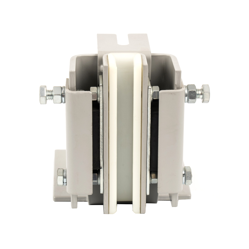
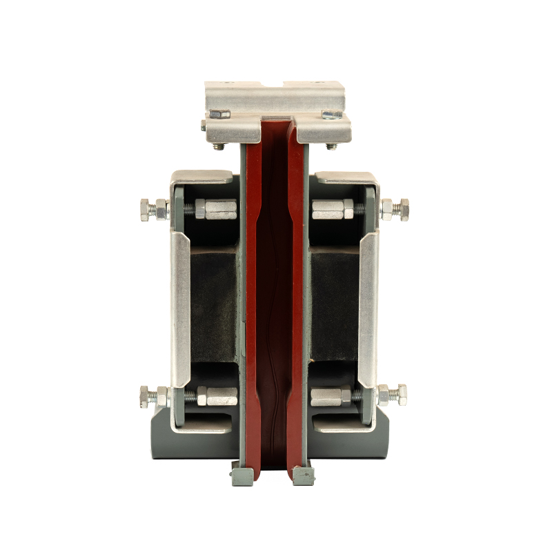
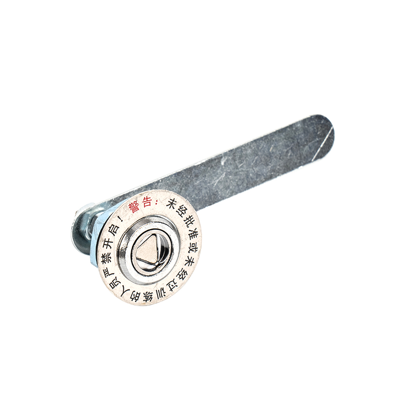
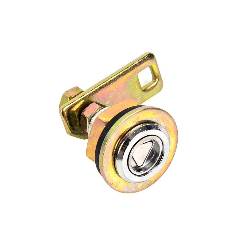
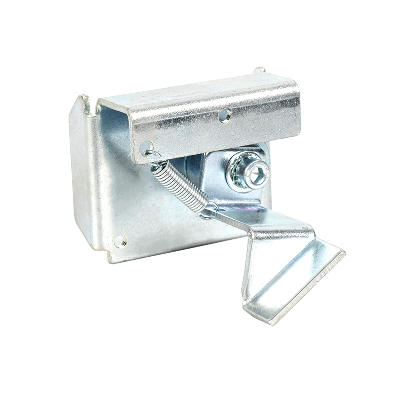
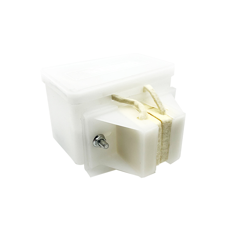
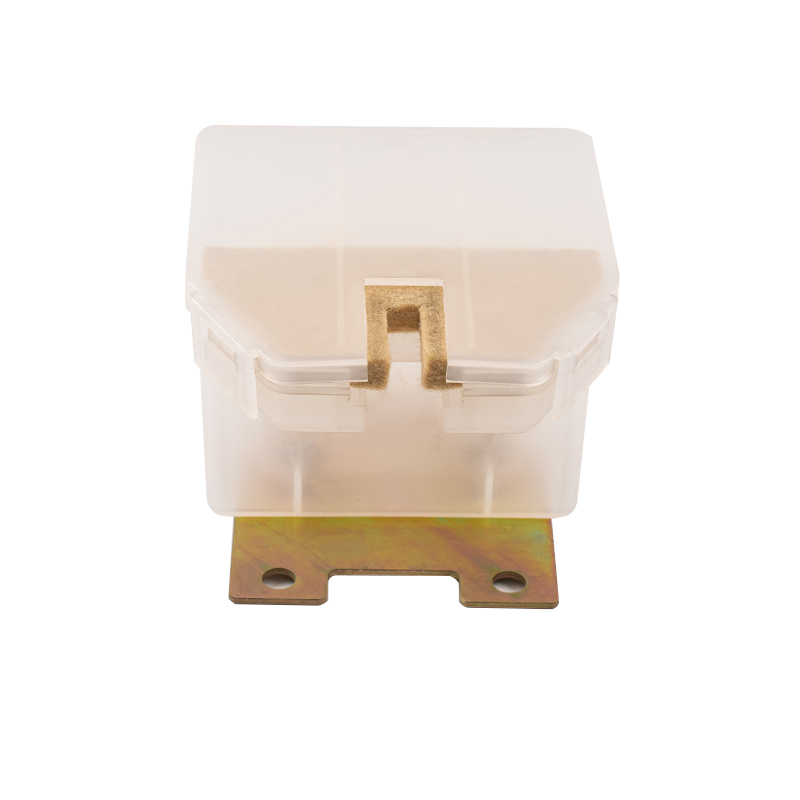
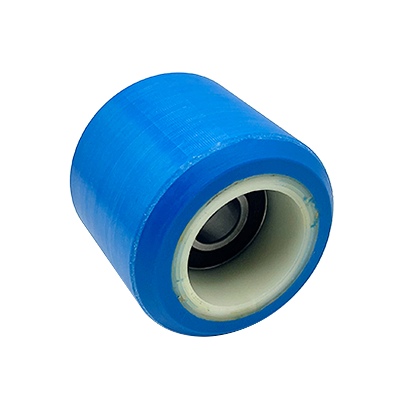
The Triangle Lock Assembly for Floor Doors is a critical safety device for elevator landing doors (sill doors). It is primarily used to lock the landing door, preventing it from being opened manually when the elevator is not stopped, thus preventing passengers from falling into the hoistway. Its name comes from its common triangular lock hook structure, which works in conjunction with the door operator interlock to provide safety control.
Content
1. Functions of the Triangle Lock Assembly for Floor Doors
Locking the landing door: When the elevator is not leveled, the triangular lock hooks onto the landing door sill, preventing external forces from forcing the door open.
Interlock Triggering: The locked state is fed back to the control system via an electrical switch (door lock contacts), allowing the elevator to operate.
Emergency Rescue: This allows a professional to unlock the door from the outside using a triangular key (e.g., to rescue trapped personnel).
Components:
|
Component Name |
Function |
Material/Characteristics |
|
Triangle Lock Hook |
Mechanically engages the floor door sill, achieving physical locking. |
Alloy Steel (Hardness HRC 40-50) |
|
Lock Arm/Link |
Transmits door operator force, driving the lock hook. |
Galvanized Stainless Steel or Carbon Steel |
|
Door Lock Electrical Switch |
Detects lock hook status and provides feedback to the control system (door lock circuit). |
Microswitch (IP54 protection) |
|
Reset Spring |
Ensures the lock hook automatically returns to the locked position. |
Stainless Steel Spring (Fatigue-Resistant) |
|
Triangle Keyhole |
Allows rescue personnel to insert a triangular key for manual unlocking. |
Brass or Hardened Steel (Vandal-Resistant) |
2. Common problems and solutions of ground door triangular lock components
Mechanical Failure
Lock hook fails to lock
Cause: Lock hook is worn and deformed, the sill lock mouth is deformed due to dust accumulation, or the return spring is broken.
Remedy: Replace the lock hook with a high-strength hook, repair the deformed sill lock mouth, and replace the stainless steel spring.
Lock hook is stuck/jerky
Cause: Rust, insufficient lubrication, or a deformed connecting rod.
Remedy: Clean with WD-40, then apply molybdenum disulfide grease to correct the deformed connecting rod.
Difficulty inserting and removing the triangular key
Cause: Rust on the lock cylinder, incorrect key specifications, or a failed internal spring.
Remedy: Spray CRC rust remover on the lock cylinder, lubricate with a standard key, and completely replace the lock cylinder assembly.
Electrical Failure
Door lock signal abnormality
Cause: Oxidation of the microswitch contacts, loose wiring, or misalignment of the mechanical arm.
Remedy: Polish the contacts or replace the IP54 protection switch, tighten and mark the wiring, and adjust the mechanical arm position.
False alarm of door lock failure
Cause: Poor switch sensitivity or short circuit. Solution: Replace a high-reliability switch and test the line insulation resistance (>0.5MΩ).
Installation Matching Issue
Lock hook insertion depth insufficient
Cause: Sill installation offset, improper linkage adjustment.
Solution: Recalibrate the sill level (deviation ≤ 1mm/m) and adjust the linkage to ensure an insertion depth of ≥7mm.
Dual-Way Lock Synchronization
Cause: Linkage mechanism misalignment.
Solution: Synchronize the double lock hook linkages to ensure the closing time difference is <0.5 seconds.
3. Precautions for installing the ground door triangular lock assembly
Pre-installation Preparation
Tool and Material Inspection
Ensure all specialized installation tools (such as a torque wrench, level, and feeler gauge) are available.
Verify that the lock assembly model matches the elevator specifications (pay particular attention to the alignment between the T-type/V-type lock hook and the guide rail type).
Inspect the lock hook, connecting rod, and other key components for transport damage.
Confirm the installation environment
Remove debris from the sill groove (such as concrete debris, metal shavings, etc.).
Check the levelness of the floor door sill mounting surface (deviation should be ≤ 1 mm/m).
Ensure adequate lighting in the work area; use temporary work lights if necessary.
Key Mechanical Installation Points
Benchmark Positioning
Use a laser line projector to determine the level. Align the centerline of the lock hook with the sill lock.
During pre-installation, do not tighten the bolts yet; perform a manual opening and closing test.
Lock hook installation
Ensure the engagement depth between the lock hook and the sill lock is ≥7mm (measured with a depth gauge).
Adjust the angle of the lock hook bevel to ensure uniform contact when closed (contact area >80%).
Mark the bolts for loosening after tightening (recommended torque 30-50 N·m).
Adjust the linkage system
Allow a 0.5-1mm thermal expansion margin for the linkage length.
Check the rotational flexibility of each hinge point (swing angle deviation ≤2°).
Synchronize the linkage mechanism of the two-way lock to ensure actuation time difference of <0.3 seconds.


 English
 中文简体
中文简体
