1. Overview of Escalator Rollers
Escalator rollers are key load-bearing components installed on both sides of the step chain or steps and rolling along the guide rails. They have the dual functions of guiding the running trajectory of the steps and dispersing the load. As the core transmission element in the escalator motion mechanism, the performance of the roller directly affects the operating efficiency, stability and safety of the entire escalator system. According to the installation position and functional differences, escalator rollers can usually be divided into multiple types such as step main wheels, step auxiliary wheels, drive wheels and tension wheels. Each roller has its specific structural characteristics and performance requirements.
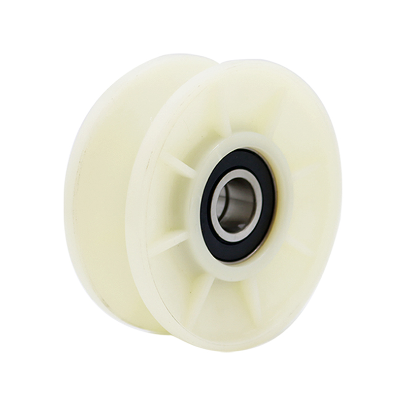
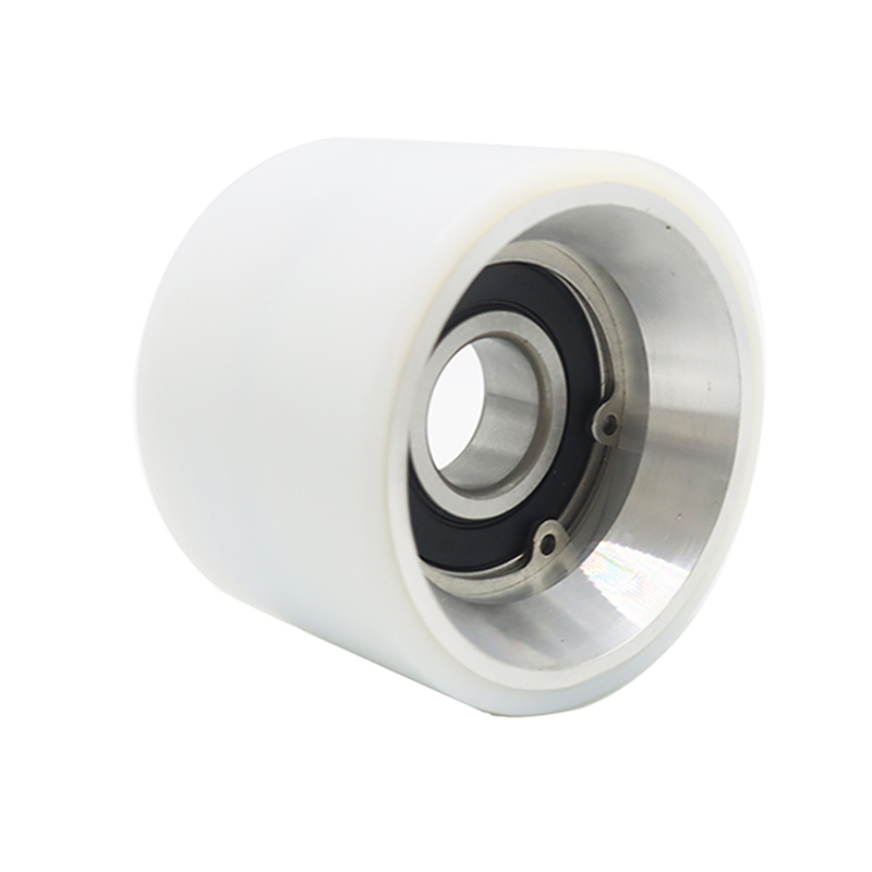
The basic structure of the roller usually includes four parts: hub, rim, bearing and sealing assembly. The hub is the central support structure of the roller, connected to the axle pin through the bearing to achieve rotational motion; the rim is the part that directly contacts the guide rail, and its material hardness and shape design determine the rolling resistance and wear resistance; high-quality ball bearings ensure that the roller rotates flexibly and smoothly; and the precision-designed sealing system prevents dust, moisture and other pollutants from invading the bearing interior, extending the service life. Modern high-performance rollers often use an integrated molding process, and the matching accuracy between the components can reach 0.01mm level, ensuring smooth and noiseless operation.
From the perspective of material development, escalator rollers have undergone a major transformation from metal to composite materials. Early rollers mostly used cast iron or steel rims, which were strong but heavy and noisy. After the 1980s, engineering plastics such as nylon and polyurethane began to be used in roller manufacturing, reducing operating noise and weight. Today's rollers use special composite materials, such as glass fiber reinforced nylon, carbon fiber composite materials, etc., which have excellent self-lubrication and anti-fatigue properties while maintaining high strength.
The technical parameters of the roller are the key indicators to measure its performance, mainly including:
- Diameter size (usually 70-120mm)
- Rated load (single roller can reach 150-300kg)
- Allowable speed (generally not more than 200rpm)
- Operating temperature range (-30℃ to +60℃)
- Hardness index (Shore D hardness 60-75 degrees)
- Friction coefficient (dynamic friction coefficient is usually less than 0.1)
These parameters need to be selected and matched according to the working conditions such as the inclination angle of the escalator (usually 30° or 35°), lifting height, running speed and expected passenger flow.
With the continuous advancement of escalator technology, the design concept and manufacturing process of rollers as key moving parts are also continuously innovating. From the initial simple function realization to the current performance optimization, intelligent monitoring and energy saving and environmental protection, the development trajectory of roller technology reflects the general trend of the entire industry towards efficiency, safety and intelligence. Understanding the basic characteristics and technical points of rollers is an important basis for ensuring the safe and economical operation of escalators.
Escalator Roller
Escalator Roller: A Complete Analysis of Structure, Function and Maintenance
- Overview of Escalator Rollers
Escalator rollers are key load-bearing components installed on both sides of the step chain or steps and rolling along the guide rails. They have the dual functions of guiding the running trajectory of the steps and dispersing the load. As the core transmission element in the escalator motion mechanism, the performance of the roller directly affects the operating efficiency, stability and safety of the entire escalator system. According to the installation position and functional differences, escalator rollers can usually be divided into multiple types such as step main wheels, step auxiliary wheels, drive wheels and tension wheels. Each roller has its specific structural characteristics and performance requirements.
The basic structure of the roller usually includes four parts: hub, rim, bearing and sealing assembly. The hub is the central support structure of the roller, connected to the axle pin through the bearing to achieve rotational motion; the rim is the part that directly contacts the guide rail, and its material hardness and shape design determine the rolling resistance and wear resistance; high-quality ball bearings ensure that the roller rotates flexibly and smoothly; and the precision-designed sealing system prevents dust, moisture and other pollutants from invading the bearing interior, extending the service life. Modern high-performance rollers often use an integrated molding process, and the matching accuracy between the components can reach 0.01mm level, ensuring smooth and noiseless operation.
From the perspective of material development, escalator rollers have undergone a major transformation from metal to composite materials. Early rollers mostly used cast iron or steel rims, which were strong but heavy and noisy. After the 1980s, engineering plastics such as nylon and polyurethane began to be used in roller manufacturing, reducing operating noise and weight. Today's rollers use special composite materials, such as glass fiber reinforced nylon, carbon fiber composite materials, etc., which have excellent self-lubrication and anti-fatigue properties while maintaining high strength.
The technical parameters of the roller are the key indicators to measure its performance, mainly including:
Diameter size (usually 70-120mm)
Rated load (single roller can reach 150-300kg)
Allowable speed (generally not more than 200rpm)
Operating temperature range (-30℃ to +60℃)
Hardness index (Shore D hardness 60-75 degrees)
Friction coefficient (dynamic friction coefficient is usually less than 0.1)
These parameters need to be selected and matched according to the working conditions such as the inclination angle of the escalator (usually 30° or 35°), lifting height, running speed and expected passenger flow.
With the continuous advancement of escalator technology, the design concept and manufacturing process of rollers as key moving parts are also continuously innovating. From the initial simple function realization to the current performance optimization, intelligent monitoring and energy saving and environmental protection, the development trajectory of roller technology reflects the general trend of the entire industry towards efficiency, safety and intelligence. Understanding the basic characteristics and technical points of rollers is an important basis for ensuring the safe and economical operation of escalators.
2. Working principle and function of rollers
As the core component of power transmission and motion guidance, the working mechanism of escalator rollers involves complex mechanical principles and precision mechanical interactions. A deep understanding of the functional implementation of rollers in escalator systems not only helps with correct use and maintenance, but also provides a theoretical basis for fault diagnosis and performance optimization. From a dynamic perspective, rollers simultaneously assume multiple functional roles during the operation of escalators, and each role has its specific working principle and technical requirements.
Load transfer function is the most basic mechanism of rollers. When the escalator is running, the load (passenger weight) on each step is transferred to the rollers on both sides through the step frame, and then distributed to the guide rail system by the rollers. In this process, a single roller may bear a dynamic load of up to 200-300kg, and the load direction changes with the position of the escalator: in the horizontal section, it is mainly vertical pressure, and in the inclined section, it is decomposed into the pressure of the vertical guide rail and the tangential force of the parallel guide rail. Modern rollers use multi-point support design and optimized load distribution to make the contact stress uniform and avoid local overload. Calculations show that the maximum contact stress of rollers with curved rim profiles can be reduced by 30-40% compared to flat rims, significantly extending their service life.
The motion guide function ensures that the steps run accurately along the predetermined trajectory. The kinematic pair composed of the roller and the guide rail needs to strictly control the radial clearance (usually 0.5-1mm) to ensure smooth operation and prevent excessive shaking. In the turning part of the escalator (such as the transition area between the upper and lower horizontal sections and the inclined section), the roller needs to adapt to the change in the curvature of the guide rail and reduce sliding friction through the self-aligning design.
The kinetic energy conversion efficiency directly affects the energy consumption performance of the escalator. During the rolling process, the roller will convert part of the mechanical energy into heat energy (rolling resistance) and sound energy (operating noise). High-quality rollers reduce this energy loss through a variety of technical means: using low friction coefficient materials; optimizing the hardness of the rim to minimize the deformation energy loss; improving manufacturing accuracy to reduce vibration loss. The vibration damping characteristics are related to ride comfort and component life. During operation, the roller needs to absorb energy from various vibration sources such as guide rail unevenness and drive impact to prevent vibration from being transmitted to the steps and passengers. The roller achieves excellent vibration control through a multi-stage shock-absorbing design: the elastic rim material absorbs high-frequency vibrations; the buffer layer between the hub and the rim handles medium-frequency vibrations; and the overall structural damping characteristics suppress low-frequency vibrations.
The roller will accumulate heat due to friction during continuous operation, especially under high load and high speed conditions, the rim temperature may rise to 60-80°C. Excessive temperature will accelerate material aging and reduce mechanical properties. High-quality rollers achieve heat balance in many ways: selecting materials with high thermal conductivity (such as aluminum-based composite materials); designing heat dissipation structures (such as rim ventilation grooves); matching appropriate wheel diameter sizes (linear speed controlled at 0.5-1.5m/s), etc. Infrared thermal imaging analysis shows that the optimized roller can maintain stable mechanical properties at operating temperature, avoiding performance degradation caused by thermal decay.
The wear-balancing mechanism extends the maintenance cycle of the roller system. Due to the different operating conditions of each section of the escalator (horizontal section and inclined section, upside and downside), the wear of the roller is often uneven. The advanced roller system uses a rotatable wheel frame design and regular transposition maintenance to make the wear of each roller uniform. The working principle of the escalator roller embodies the essence of precision mechanical engineering. Through carefully designed structures, strictly selected materials and accurately calculated parameters, it achieves a perfect balance of multiple functions such as load transfer, motion guidance, energy conversion and vibration control.
3. Common Fault Analysis of Escalator Rollers
Common Faults and Diagnostic Methods
As a high-load moving part, escalator rollers are bound to have various forms of faults and performance degradation during long-term operation. Accurately identifying these types of faults, understanding their causes and mastering scientific diagnostic methods are the key to ensuring the safe operation and timely maintenance of escalators. Through systematic fault analysis and prevention, the service life of rollers can be significantly extended, the risk of unexpected downtime can be reduced, and the overall reliability of escalators can be improved. This section will analyze in detail the typical failure modes, causes, identification techniques and maintenance countermeasures of rollers.
Rim wear is the most common form of roller failure, which is manifested as a gradual loss of working surface material and a change in geometric shape. According to the wear mechanism, it can be divided into three categories: adhesive wear (microscopic protrusions on the surface of the material shear each other), abrasive wear (hard particles scratch the surface) and fatigue wear (cyclic stress causes surface peeling). Under normal use, the annual wear of the rim of a high-quality roller should be less than 0.5mm. When the wear exceeds 2mm or uneven wear occurs, it needs to be replaced. During on-site inspection, the thickness of the wheel rim can be measured with a caliper, and the degree of wear can be determined by comparing it with the original size.
Bearing failure is another major cause of roller abnormality, which is manifested by rotation stagnation, abnormal noise, and excessive radial clearance. Bearing failure usually goes through four stages of development: initial lubrication failure (grease drying or contamination); followed by micro-flaking (fatigue pitting on the rolling element and raceway surface); then macro-flaking (visible pits and material loss); and finally the cage breaks or is completely stuck. When using a vibration analyzer to detect the roller bearing status, if the vibration value in the high frequency band (3-10kHz) exceeds 2.5m/s², it often indicates that the bearing has entered the fault development stage.
Surface cracking is a unique aging phenomenon of polyurethane rollers, which is manifested as a network of micro-cracks on the wheel rim surface. This is the result of the combined effects of ultraviolet aging and thermal oxidation aging, which will reduce the strength and elasticity of the material. When the crack density exceeds 5/cm or the depth reaches 1mm, the roller should be replaced. Infrared thermal imagers can effectively detect early signs of aging. Areas with abnormally high local temperatures (15°C above ambient temperature) often indicate that cracks are about to appear.
Rim deformation is usually caused by local overload or high temperature softening, which manifests as a rounded contour or flat area. Use a dial indicator to measure the radial runout of the roller. If it exceeds 0.3mm, it means that the deformation exceeds the standard. This failure is particularly common in shopping malls and other places. The concentrated load of shopping carts and long-term continuous operation are the main causes. Thermal imaging analysis shows that the operating temperature of deformed rollers is often 20-30°C higher than that of normal rollers, forming a vicious cycle. Solutions include: using high-heat-resistant materials (such as PI composite materials); increasing the number of rollers to disperse the load; setting running intervals to avoid heat accumulation.
Abnormal noise is an intuitive warning signal of roller failure. Different sound characteristics correspond to different problems: regular "clicking" sounds are mostly caused by bearing damage; continuous "buzzing" sounds may be caused by uneven wear of the rim; sharp "squeaking" sounds often indicate insufficient lubrication. Professional maintenance personnel can use acoustic cameras or vibration spectrum analyzers to accurately locate the source of noise and determine the type of fault. Actual measurements show that the operating noise of a normal roller should be less than 65dB(A). If it exceeds 75dB(A), a detailed inspection is required.
Although seal failure is not easy to observe directly, it is very harmful and will cause contaminants to enter and accelerate bearing wear. Diagnostic methods include: checking whether the seal lip is intact; testing the grease contamination (ISO code exceeding 18/16/13 requires attention); observing whether the wheel hub has traces of grease leakage. Advanced fluorescent leak detection can quickly evaluate the sealing performance in the shutdown state. After adding fluorescent agent to the grease, use ultraviolet light to check the leakage point.
Failures caused by improper installation are often ignored, but may have serious consequences. Common installation problems include: bending of the shaft pin (causing eccentric load); improper tightening torque (too loose causes shaking, too tight causes excessive bearing preload); lack of anti-loosening measures (loose nuts cause accidents). Using torque wrenches and laser alignment instruments can effectively prevent such problems.
The systematic fault diagnosis process should include the following steps:
- Visual inspection: wheel rim wear, cracks, deformation; seal integrity; lubrication condition
- Manual test: rotation flexibility; radial/axial clearance; abnormal sound
- Instrument detection: vibration spectrum analysis; temperature distribution measurement; noise level assessment
- Performance test: running resistance measurement; dynamic vibration test; load distribution verification
- Data analysis: comparison of historical data; evaluation of development trends; prediction of remaining life


 English
 中文简体
中文简体
